Detail
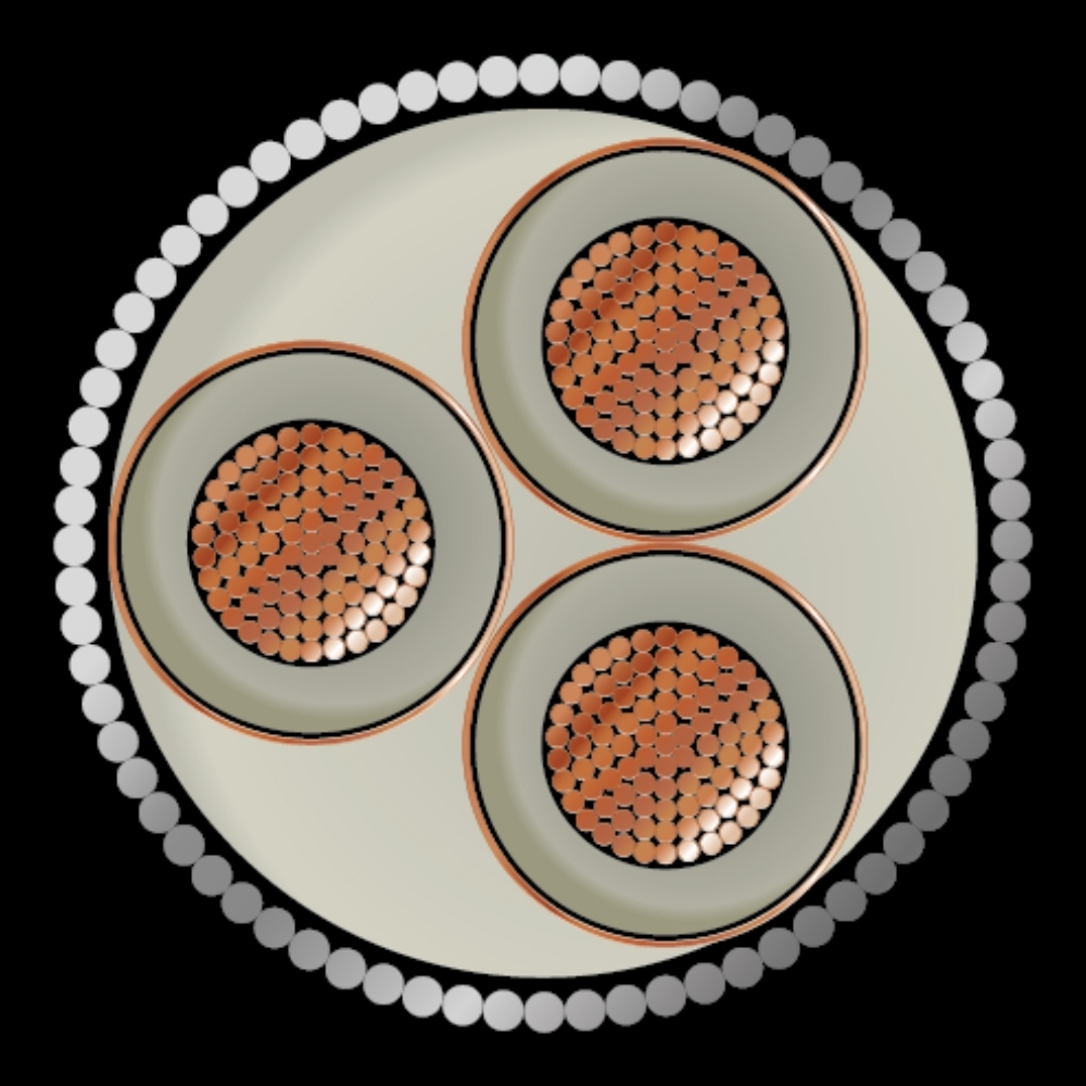
Medium voltage cables are rated 6/10 (12) KV (Suitable for 6.35/11 (12) KV Earthed System), 8.7/15 KV and 12/20 (24) KV (Suitable for 12.7/22 (24) KV Earthed System) manufactured in accordance with IEC 60502 (Part 2). Whereas 18/30 (36) KV (Suitable for 19/33 (36) kV Earthed System) manufactured in accordance with IEC 502.
CONDUCTORS
A conductor is the metallic part of cables that is carrying the electric current.
Material of Conductor could be:
The conductor structure is complying with the requirements of BS EN 60228 (IEC 60228), class 2, stranded, Round and Compacted.
CONDUCTOR SCREEN (STRESS CONTROL LAYER)
Over the metallic conductor, a layer of cross linked semi-conducting compound is extruded directly during the XLPE insulation extrusion. This layer acts to smooth out any irregularities and thus reduces the probability of protrusions into the insulating layer. Such protrusions into the insulation or into the semi-conducting layer increase the localized stress that may exceed the long-term breakdown strength of the insulation, so the semi-conductive layer is acting as a stress control layer.
INSULATION
Each core conductor is insulated by extruded cross-linked polyethylene conforming to IEC 60502-2. The insulation thickness is selected based on the designated voltage rate complying with IEC 60502-2. All the three layers (Conductor screen, XLPE insulation and Insulation screen) are extruded together through Triple extrusion.
INSULATION SCREEN (STRESS RELIEF LAYER)
Over the insulation, an extruded layer of cross linked semi-conducting compound is applied. This layer, which has a very smooth surface, is a transition from the insulating material where the electric field exists to a conductive metallic screen, where the electric field is zero, so it will reduce the stress enhancement at the insulation layer.
The insulation’s shield layer could be bonded to the insulation or strippable type for easily removable to facilitate splicing and terminating. The volume resistivity of this external layer is limited to 500 meter-ohms.
METALLIC SCREENING / SHIELDING
The metallic screening over insulation semi-conductive layer is necessary to cancel out the electric field outside the cable and to provide a low resistance path for charging current to flow to ground. When the screening bonded to earth it will also carry out the short circuit fault current.
CABLE ASSEMBLY
For 3 core cable, the screened cores will have identification tape (Red, Yellow & Blue) under the metallic screen, then the cores are laid up together to form the laid up cable cores. A non-hygroscopic polypropylene filler is applied between laid up cores to provide a circular shape to the cable.
Polypropylene tape(s) is used as a barrier tape over the laid up cores. Such tape will bind the cores together and prevent them from opening out, acts as a separator between different polymers used in a cable and works as a heat barrier between the cores and the extruded bedding.
BEDDING
Extruded bedding layer serves as a bedding under cable Armouring to protect the laid up cores and as a separation sheath. The bedding is an extruded PVC complying with ST2 to IEC 60502-2 or type LT2 to BS 7655:6.1 for LSZH cables.
ARMOURING
The cable intended for tray application is protected enough and does not require armour in general, while it is recommended to have armour for the cable intended for Direct Burial Application. The armour provides mechanical protection against crushing forces. Armour also can serve as an Earth Continuity Conductor (ECC). The Armouring type consist of:
OUTER SHEATH (OUTER JACKET)
It is the outer protection part of the cable against the surrounding environment. Several materials can be used as over sheath based on the intended application.
-
General purpose PVC Type ST2 compound as specified in IEC 60502-2, or its equivalent PVC Type 9 to BS 7655:4.2.
-
Medium density Polyethylene MDPE compound fulfill and exceed the requirements of Type ST7 of IEC 60502-2 for cables that require to be abrasion resistant, protected against water ingress and strong Environmental Stress Crack Resistant (ESCR).
-
Low smoke zero halogen compounds complying with Types LTS 1 & LTS 4 to BS 7655:6.1 for cables installed in intrinsically safe locations and where the cables require to be low smoke, low fume and low toxic gas emitting in case of fire.
-
The standard sheath color is Black, meanwhile other color such as Red can also be provided as per customer request.
-
When the cable is required to ant-termite / anti-vermin, a special additive is added to the sheathing compound.
-
All cables produced at Newage Cables Company with PVC or Halogen free jackets are complying with the flame retardant test to IEC 60332.
NOMINAL VOLTAGE
The Nominal voltage is to be expressed with two values of alternative current Uo/U in V (volt)
Uo/U
:
Phase To Earth Voltage
Uo
:
Voltage between Conductor & Earth
U
:
Voltage between Phases (Conductors)
RESISTANCE
The D.C resistance of the cables depends upon its cross-sectional area of the conductor. These values slightly vary with the change in temperature. The required values are normally given at 20°C. However the values can be converted to 20°C by using the formula.
Rt
=
R20 x [1 + α (t - 20)]
Ω/km
Rt
:
Conductor DC Resistance at t°C
Ω/km
R20
:
Conductor DC Resistance at 20°C
Ω/km
t
:
Operating Temperature
°C
α
:
Resistance Temperature Coefficient
= 0.00393 for Copper
= 0.00403 for Aluminium
Generally DC resistance is based on IEC 60228.
To calculate AC resistance of the conductor at the operating temperature as the following:
RAC
=
Rt x [ 1+ ys + yp ]
ys
:
Skin Effect Factor
yp
:
Proximity Effect
Generally AC resistance is based on IEC 60287
CAPACITANCE
C=
εr18 ln D/d
μF/km
C
:
Operating Capacitance
μF/km
D
:
Diameter over insulation
mm
d
:
Conductor Diameter
mm
εr
:
Relative permittivity of insulation
εr
=
2.3 for XLPE
INDUCTANCE
L
=
K + 0.2 ln (2s/d)
mH/km
L
:
Inductance
mH/km
K
:
Constant depends on number of wires of conductor
d
:
Conductor diameter
S
:
Axial spacing between cables (Trefoil formation)
S
:
1.26 x axial spacing between cables (Flat formation)
REACTANCE
The inductive reactance per phase of a cable may be obtained by the formula:
X
=
2 π f L x 10-3
Ω/km
X
:
Reactance
Ω/km
f
:
Frequency
Hz
L
:
Inductance
mH/km
IMPEDANCE
Z
=
√(R2ac + X2)
Ω/km
Z
:
Phase Impedance of Cable
Ω/km
Rac
:
AC Resistance at Operating Temperature
Ω/km
X
:
Reactance
Ω/km
INSULATION RESISTANCE
R=
1000 x LN (D/d)2 x π
MΩ.km
R
:
Insulation Resistance at 20° C
MΩ.km
D
:
Insulated Conductor Diameter
mm
d
:
Conductor Diameter
mm
CHARGING CURRENT
I
=
Uo x 2 π f x C x 10-6
A/km
I
:
Charging Current
A/km
Uo
:
Voltage Between Phase & Earth
V
C
:
Capacitance to Neutral
μF/km
DIELECTRIC LOSSES
D
=
2 π f C Uo2 tan δ 10-6
watt/km/phase
D
:
Dielectric Losses
watt/km/phase
Uo
:
Voltage Between Phase & Earth
V
C
:
Capacitance to Neutral
μF/km
tan δ
:
Dielectric Power Factor
CABLE SHORT CIRCUIT CAPACITY
ISC(t)
=
ISC(1) / √t
kA
ISC(t)
:
Short Circuit for t Second
kA
ISC(1)
:
Short Circuit for 1 Second
kA
VOLTAGE DROP
When the current flows in conductor, there is a voltage drop between the ends of the conductor. Voltage drop can be calculated by using the following formula:
Vd=
mV x I x L1000
I
=
Current in Amperes
L
=
Route Length in Meters
mV
=
Approximate Volt Drop / Ampere / Meter
Diameters of Stranded Circular Compacted
Copper & Aluminium Conductors Conforming to IEC 60228
Medium voltage cables are rated 6/10 (12) KV (Suitable for 6.35/11 (12) KV Earthed System), 8.7/15 KV and 12/20 (24) KV (Suitable for 12.7/22 (24) KV Earthed System) manufactured in accordance with IEC 60502 (Part 2). Whereas 18/30 (36) KV (Suitable for 19/33 (36) kV Earthed System) manufactured in accordance with IEC 502.
CONDUCTORS
A conductor is the metallic part of cables that is carrying the electric current.
Material of Conductor could be:
The conductor structure is complying with the requirements of BS EN 60228 (IEC 60228), class 2, stranded, Round and Compacted.
CONDUCTOR SCREEN (STRESS CONTROL LAYER)
Over the metallic conductor, a layer of cross linked semi-conducting compound is extruded directly during the XLPE insulation extrusion. This layer acts to smooth out any irregularities and thus reduces the probability of protrusions into the insulating layer. Such protrusions into the insulation or into the semi-conducting layer increase the localized stress that may exceed the long-term breakdown strength of the insulation, so the semi-conductive layer is acting as a stress control layer.
INSULATION
Each core conductor is insulated by extruded cross-linked polyethylene conforming to IEC 60502-2. The insulation thickness is selected based on the designated voltage rate complying with IEC 60502-2. All the three layers (Conductor screen, XLPE insulation and Insulation screen) are extruded together through Triple extrusion.
INSULATION SCREEN (STRESS RELIEF LAYER)
Over the insulation, an extruded layer of cross linked semi-conducting compound is applied. This layer, which has a very smooth surface, is a transition from the insulating material where the electric field exists to a conductive metallic screen, where the electric field is zero, so it will reduce the stress enhancement at the insulation layer.
The insulation’s shield layer could be bonded to the insulation or strippable type for easily removable to facilitate splicing and terminating. The volume resistivity of this external layer is limited to 500 meter-ohms.
METALLIC SCREENING / SHIELDING
The metallic screening over insulation semi-conductive layer is necessary to cancel out the electric field outside the cable and to provide a low resistance path for charging current to flow to ground. When the screening bonded to earth it will also carry out the short circuit fault current.
CABLE ASSEMBLY
For 3 core cable, the screened cores will have identification tape (Red, Yellow & Blue) under the metallic screen, then the cores are laid up together to form the laid up cable cores. A non-hygroscopic polypropylene filler is applied between laid up cores to provide a circular shape to the cable.
Polypropylene tape(s) is used as a barrier tape over the laid up cores. Such tape will bind the cores together and prevent them from opening out, acts as a separator between different polymers used in a cable and works as a heat barrier between the cores and the extruded bedding.
BEDDING
Extruded bedding layer serves as a bedding under cable Armouring to protect the laid up cores and as a separation sheath. The bedding is an extruded PVC complying with ST2 to IEC 60502-2 or type LT2 to BS 7655:6.1 for LSZH cables.
ARMOURING
The cable intended for tray application is protected enough and does not require armour in general, while it is recommended to have armour for the cable intended for Direct Burial Application. The armour provides mechanical protection against crushing forces. Armour also can serve as an Earth Continuity Conductor (ECC). The Armouring type consist of:
OUTER SHEATH (OUTER JACKET)
It is the outer protection part of the cable against the surrounding environment. Several materials can be used as over sheath based on the intended application.
-
General purpose PVC Type ST2 compound as specified in IEC 60502-2, or its equivalent PVC Type 9 to BS 7655:4.2.
-
Medium density Polyethylene MDPE compound fulfill and exceed the requirements of Type ST7 of IEC 60502-2 for cables that require to be abrasion resistant, protected against water ingress and strong Environmental Stress Crack Resistant (ESCR).
-
Low smoke zero halogen compounds complying with Types LTS 1 & LTS 4 to BS 7655:6.1 for cables installed in intrinsically safe locations and where the cables require to be low smoke, low fume and low toxic gas emitting in case of fire.
-
The standard sheath color is Black, meanwhile other color such as Red can also be provided as per customer request.
-
When the cable is required to ant-termite / anti-vermin, a special additive is added to the sheathing compound.
-
All cables produced at Newage Cables Company with PVC or Halogen free jackets are complying with the flame retardant test to IEC 60332.
NOMINAL VOLTAGE
The Nominal voltage is to be expressed with two values of alternative current Uo/U in V (volt)
Uo/U
:
Phase To Earth Voltage
Uo
:
Voltage between Conductor & Earth
U
:
Voltage between Phases (Conductors)
RESISTANCE
The D.C resistance of the cables depends upon its cross-sectional area of the conductor. These values slightly vary with the change in temperature. The required values are normally given at 20°C. However the values can be converted to 20°C by using the formula.
Rt
=
R20 x [1 + α (t - 20)]
Ω/km
Rt
:
Conductor DC Resistance at t°C
Ω/km
R20
:
Conductor DC Resistance at 20°C
Ω/km
t
:
Operating Temperature
°C
α
:
Resistance Temperature Coefficient
= 0.00393 for Copper
= 0.00403 for Aluminium
Generally DC resistance is based on IEC 60228.
To calculate AC resistance of the conductor at the operating temperature as the following:
RAC
=
Rt x [ 1+ ys + yp ]
ys
:
Skin Effect Factor
yp
:
Proximity Effect
Generally AC resistance is based on IEC 60287
CAPACITANCE
C=
εr18 ln D/d
μF/km
C
:
Operating Capacitance
μF/km
D
:
Diameter over insulation
mm
d
:
Conductor Diameter
mm
εr
:
Relative permittivity of insulation
εr
=
2.3 for XLPE
INDUCTANCE
L
=
K + 0.2 ln (2s/d)
mH/km
L
:
Inductance
mH/km
K
:
Constant depends on number of wires of conductor
d
:
Conductor diameter
S
:
Axial spacing between cables (Trefoil formation)
S
:
1.26 x axial spacing between cables (Flat formation)
REACTANCE
The inductive reactance per phase of a cable may be obtained by the formula:
X
=
2 π f L x 10-3
Ω/km
X
:
Reactance
Ω/km
f
:
Frequency
Hz
L
:
Inductance
mH/km
IMPEDANCE
Z
=
√(R2ac + X2)
Ω/km
Z
:
Phase Impedance of Cable
Ω/km
Rac
:
AC Resistance at Operating Temperature
Ω/km
X
:
Reactance
Ω/km
INSULATION RESISTANCE
R=
1000 x LN (D/d)2 x π
MΩ.km
R
:
Insulation Resistance at 20° C
MΩ.km
D
:
Insulated Conductor Diameter
mm
d
:
Conductor Diameter
mm
CHARGING CURRENT
I
=
Uo x 2 π f x C x 10-6
A/km
I
:
Charging Current
A/km
Uo
:
Voltage Between Phase & Earth
V
C
:
Capacitance to Neutral
μF/km
DIELECTRIC LOSSES
D
=
2 π f C Uo2 tan δ 10-6
watt/km/phase
D
:
Dielectric Losses
watt/km/phase
Uo
:
Voltage Between Phase & Earth
V
C
:
Capacitance to Neutral
μF/km
tan δ
:
Dielectric Power Factor
CABLE SHORT CIRCUIT CAPACITY
ISC(t)
=
ISC(1) / √t
kA
ISC(t)
:
Short Circuit for t Second
kA
ISC(1)
:
Short Circuit for 1 Second
kA
VOLTAGE DROP
When the current flows in conductor, there is a voltage drop between the ends of the conductor. Voltage drop can be calculated by using the following formula:
Vd=
mV x I x L1000
I
=
Current in Amperes
L
=
Route Length in Meters
mV
=
Approximate Volt Drop / Ampere / Meter
Diameters of Stranded Circular Compacted
Copper & Aluminium Conductors Conforming to IEC 60228